Planning a CCTV system from scratch can feel like a puzzle with too many pieces. You need the right camera placement to cover every blind spot, the correct lens focal length to capture details at a given distance, and a cable run that actually reaches your PoE switch without exceeding the 100-metre limit. For years, the industry relied on manual sketches and spreadsheets. Then came dedicated design tools that brought order to the process. One approach that has quietly gained traction among installers and consultants is using a layout that behaves like a cctv cad environment - a way to draw your site, drop in cameras, and see the coverage area update in real time.
If you have ever stood in a warehouse with a tape measure and a notebook, trying to guess where an IP camera with a 2.8 mm lens will point, you know how easy it is to misjudge the field of view. A few metres off and you are staring at a pillar instead of the entrance. A cctv cad approach changes that. You import a floor plan or a satellite image, mark walls and obstacles, and then place virtual cameras. The tool calculates the field of view for you, based on the lens focal length and the sensor size. You can shift a camera a metre to the left and see the coverage area shrink or expand. That kind of feedback saves time and reduces the chance of a costly mistake during installation.
Why a Structured Design Tool Beats a Spreadsheet
Many security integrators start a project by listing cameras in a spreadsheet and drawing rough arrows on a printed map. That method works for a small house with four analogue cameras, but it falls apart on a commercial site with twenty IP cameras, each at a different resolution and with different night vision requirements. You end up with a coverage gap at the loading dock because nobody noticed that the 12 mm lens on camera 14 leaves a blind spot behind the racking.
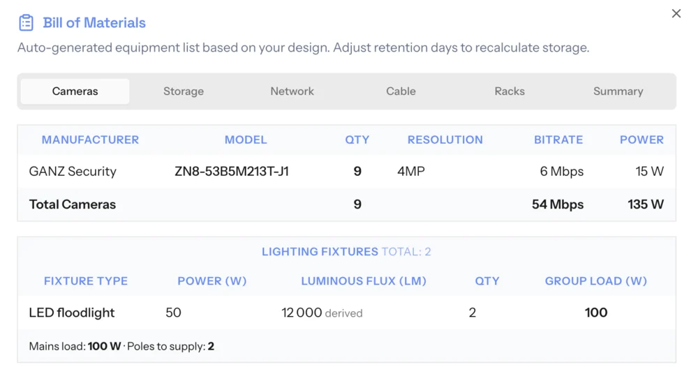
A proper design tool, especially one that acts like a cctv cad system, enforces a few good habits. First, it forces you to define the coverage area for each camera. You mark the zone that needs monitoring - a door, a corridor, a cash register - and then the tool tells you if the chosen camera model and lens can cover it at the required resolution. Second, it tracks the cable run from each camera back to the nearest PoE switch. If the run exceeds 100 metres, you either move the switch or plan a mid-span extender. Third, it keeps a running bill of materials. Every time you add a camera, the tool updates the list of cameras, lenses, brackets, cables, and connectors. That bill of materials feeds directly into your client proposal, so the customer sees exactly what they are paying for.
Camera Placement and Field of View
Camera placement is where theory meets reality. You might want to cover the entire car park with one 5 MP camera, but the field of view from that mounting height and distance gives you a pixel density too low for number plate recognition. So you split the area into two coverage zones, each with its own camera. A design tool lets you draw those zones and then pick the right lens focal length for each. For a narrow corridor, a 6 mm lens might be perfect. For a lobby, a 2.8 mm lens gives a wide view but with some barrel distortion. The trade-off is always between coverage area and the level of detail you need.

Resolution plays a big role here. A 4K camera can cover a wider area at an acceptable pixel density than a 2 MP camera can. But higher resolution means more bandwidth and more storage. H.265 helps by cutting the bitrate roughly in half compared to H.264, but you still need to size the NVR and the network accordingly. A good design tool lets you adjust the resolution per camera and see the impact on storage and bandwidth. That is the kind of practical detail that saves you from installing a system that maxes out the network in the first week.
Night Vision and Low-Light Performance
Night vision is another area where a design tool pays off. An IP camera with built-in IR can see maybe 30 metres in total darkness, but the effective range depends on the lens, the sensor sensitivity, and the scene reflectivity. If you place a camera at the far end of a yard and rely on its internal IR illuminators, you might find that the image is too dark at the edges of the coverage area. A design tool that models the IR beam pattern and shows the illumination fall-off helps you decide whether to add an external IR illuminator or move the camera closer.
Motion detection also benefits from proper planning. If a camera’s field of view includes tree branches that sway in the wind, you will get false alarms all afternoon. You can either adjust the motion detection mask in the video management system or reposition the camera so the branches fall outside the detection zone. Spotting that issue on a virtual layout is much cheaper than climbing a ladder three times to adjust the angle.
From Site Survey to Client Proposal
A typical project starts with a site survey. You walk the building, measure distances, note lighting conditions, and check where the cable runs can go. Back at the office, you open a design tool and recreate the site. This is where the real value appears. Instead of guessing, you place each camera, set its lens focal length, and watch the coverage area appear on the plan. You can export a PDF of the layout, along with a bill of materials, and include it in your client proposal. A proposal with a clear, scaled drawing gives the customer confidence. They can see exactly where each camera will point and what area it will cover.
The same drawing helps the installation crew. They do not have to interpret scribbled notes or remember a verbal instruction. They follow the plan, mount each camera at the marked position, and run the cables along the paths shown. That consistency reduces installation time and cuts down on callbacks. If the customer later asks for a change - move camera 8 two metres to the left - you update the drawing and see the impact on the coverage area instantly.
Compatibility and Standards
Modern systems mix devices from different manufacturers. An NVR from one brand might work with IP cameras from another if they both support ONVIF. But ONVIF is not always a magic bullet. Some features, like advanced motion detection or audio, may require the camera and recorder to be from the same family. A design tool that includes a database of camera models and their ONVIF compliance helps you avoid pairing a camera with an NVR that cannot control its key features. Similarly, knowing whether a camera supports H.265 or only H.264 affects your storage calculation and your choice of NVR.
For legacy systems using analogue cameras, a DVR is still the right choice. But many sites now mix analogue and IP cameras during a phased upgrade. A design tool that handles both types in the same project is useful. You can plan the cable runs for the analogue cameras separately, note where the coax meets the network cable, and show the transition on the drawing.
Practical Trade-Offs in System Design
Every security system involves compromises. You might have a limited budget, so you choose a lower resolution camera for less critical areas. Or you might have a strict cable run limit that forces you to place the PoE switch closer to the cameras, which then requires a bigger enclosure. A design tool lets you test those trade-offs before you buy anything. You can swap a 5 MP camera for a 2 MP one and see if the coverage area still meets the customer’s requirement. You can move the switch and recalculate the cable lengths. You can add a few metres of conduit and see if the bill of materials changes.
The best design tools also let you include notes about the site conditions. For example, if a wall is made of brick and the cable run needs a drill, you can mark that on the plan. If a certain area has strong backlight from a window, you can note that the camera should have wide dynamic range. These details matter during installation and during commissioning. They turn a generic drawing into a living document that the whole team can use.
Moving from a Drawing to a Working System
Once the design is approved, the next step is configuring the video management system. The camera placement plan tells you which camera covers which zone, so you can label each camera stream clearly in the VMS. You can set up motion detection zones on the same plan, aligning them with the coverage areas you defined earlier. The same goes for recording schedules and retention periods. A well-planned design makes the VMS setup faster and less error-prone.
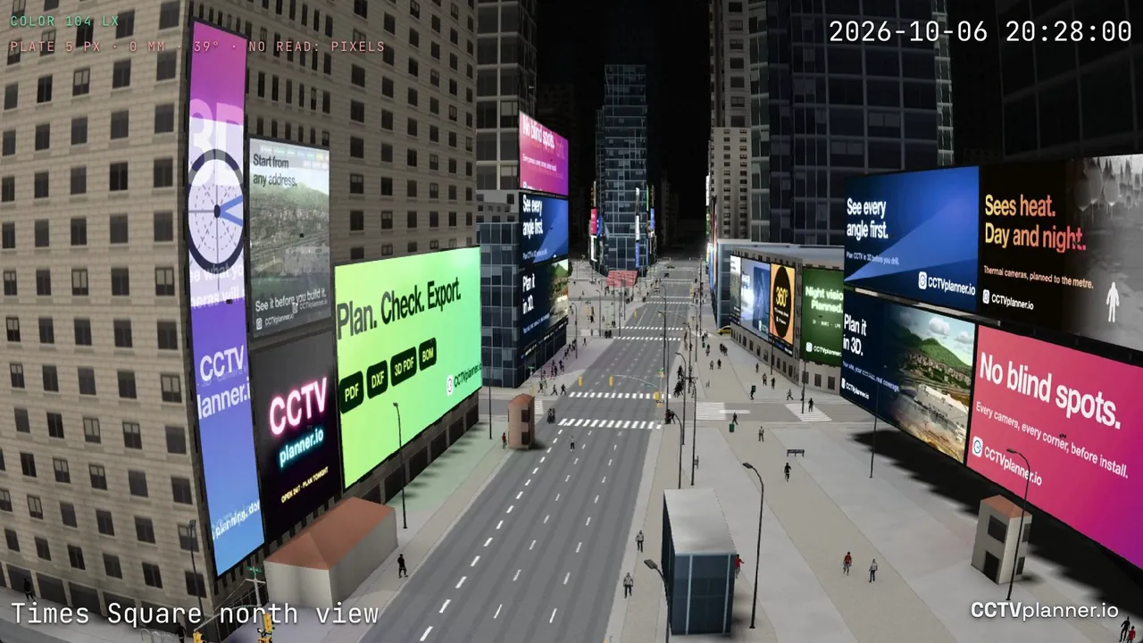
Finally, a good design tool helps you maintain the system over time. When a camera fails or a lens needs replacing, you pull up the original plan, see the exact model and lens focal length, and order the correct spare part. No more guessing from a blurry photo. The plan also helps when you expand the system later. You see where the spare network ports are, where the cable runs have capacity, and where the coverage gaps have appeared since the original installation.
Using a structured approach to CCTV design - one that behaves like a cctv cad system - is not about fancy software. It is about reducing uncertainty. It is about catching problems on a screen instead of on a ladder. It is about giving the customer a clear proposal and the installer a clear set of instructions. The tools exist, and they are free to try. The only question is whether you want to keep drawing arrows on a map or start building systems that actually work the first time.